Description
Description
This NEMA 34 Closed-Loop Stepper Motor Kit is built for demanding CNC, robotics, and automation systems. The kit includes a high-torque NEMA 34 closed-loop stepper motor, matching driver, encoder feedback, 60V power supply, motor cable, encoder cable, and RS232 debugging cable.
What’s in the Box
- 1 × NEMA 34 closed-loop stepper motor, 12.00Nm, with 1000PPR encoder
- 1 × Closed-loop stepper driver, 0–8.5A, 20–80VAC / 30–110VDC
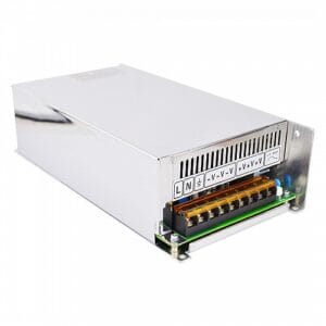
- 1 × 350W 60V 5.8A switching power supply
- 1 × 1.5m motor and encoder cable
- 1 × RS232 debugging cable
Motor Specifications
| Motor Type |
Closed-loop bipolar stepper motor |
| Frame Size |
NEMA 34 / 86 × 86mm |
| Number of Phases |
2 |
| Step Angle |
1.8° |
| Holding Torque |
12.00Nm / 1699.34oz.in |
| Rated Current / Phase |
6.0A |
| Phase Resistance |
0.59Ω ±10% |
| Inductance |
4.8mH ±20% at 1kHz |
| Body Length |
174mm |
| Shaft Diameter |
Φ14mm |
| Shaft Length |
37mm |
| Keyway Shaft Length |
25mm |
| Cable Length |
1500mm |
| Insulation Class |
Class B, 130°C |
Encoder Specifications
| Encoder Type |
Optical incremental |
| Output Circuit Type |
Differential type |
| Encoder Resolution |
1000PPR / 4000CPR |
| Output Signal Channels |
2 channels |
| Supply Voltage |
4.5V – 5V |
| Output Current |
25mA |
| Output High Voltage |
4.5V |
| Output Low Voltage |
4.2V – 4.3V |
| Maximum Output Frequency |
60kHz |
Driver Specifications
| Output Peak Current |
0 – 8.5A / 0 – 6A RMS |
| Input Voltage |
20–80VAC / 30–110VDC |
| Typical Input Voltage |
48VDC / 60VDC |
| Logic Input Current |
7 – 20mA |
| Pulse Input Frequency |
0 – 200kHz |
| Pulse Width |
2.5μs |
| Isolation Resistance |
500MΩ |
Power Supply Specifications
| Input Voltage |
115/230VAC ±20% |
| Input Frequency |
47–63Hz |
| Input Current |
40A / 230VAC |
| Output Voltage |
60VDC |
| Output Current |
5.8A |
| Rated Output Power |
350W |
| Leakage Current |
<0.5mA / 230VAC |
| Dimensions |
215 × 115 × 30mm |
| Cooling |
Forced air cooling with built-in DC fan |
| Protection |
Over-current, over-voltage, short-circuit and overheat protection |
| EMI Filter |
Internal EMI filter |
Motor Connection
| Pin |
1 |
2 |
3 |
4 |
| Pole |
A+ |
A- |
B+ |
B- |
| Color |
Black |
Green |
Red |
Blue |
Encoder Connection
| Pin |
2 |
3 |
1 |
13 |
11 |
12 |
| Encoder |
VCC |
EGND |
EA+ |
EA- |
EB+ |
EB- |
| Color |
Red |
White |
Black |
Blue |
Yellow |
Green |
Installation Notes
- Use the included regulated 60V DC power supply.
- Provide adequate cooling and airflow around the driver and power supply.
- Use shielded wiring and proper grounding for encoder signals.
- Check motor phase wiring before powering the system.
- Follow the correct wiring orientation for A+/A–, B+/B–, and encoder channels.
Resources
Tutorials / Useful Links


Reviews
There are no reviews yet.